关键词:模块,端口,双向端口,PAD
结构建模方式有 3 类描述语句: Gate(门级)例化语句,UDP (用户定义原语)例化语句和 module (模块) 例化语句。本次主要讲述使用最多的模块级例化语句。
模块
模块是 Verilog 中基本单元的定义形式,是与外界交互的接口。
模块格式定义如下:
module module_name
#(parameter_list)
(port_list) ;
              Declarations_and_Statements ;
endmodule
模块定义必须以关键字 module 开始,以关键字 endmodule 结束。
模块名,端口信号,端口声明和可选的参数声明等,出现在设计使用的 Verilog 语句(图中 Declarations_and_Statements)之前。
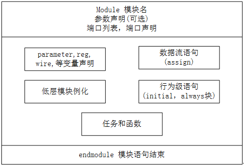
模块内部有可选的 5 部分组成,分别是变量声明,数据流语句,行为级语句,低层模块例化及任务和函数,如下图表示。这 5 部分出现顺序、出现位置都是任意的。但是,各种变量都应在使用之前声明。变量具体声明的位置不要求,但必须保证在使用之前的位置。

前面大多数仿真代码都会用到 module 声明,大家可以自行参考,这里不再做具体举例。下面介绍端口时,再做详细的仿真。
端口
端口是模块与外界交互的接口。对于外部环境来说,模块内部是不可见的,对模块的调用只能通过端口连接进行。
端口列表
模块的定义中包含一个可选的端口列表,一般将不带类型、不带位宽的信号变量罗列在模块声明里。下面是一个 PAD 模型的端口列表:
module pad(
    DIN, OEN, PULL,
    DOUT, PAD);
一个模块如果和外部环境没有交互,则可以不用声明端口列表。例如之前我们仿真时 test.sv 文件中的 test 模块都没有声明具体端口。
module test ;  //直接分号结束
    ......     //数据流或行为级描述
endmodule
端口声明
(1) 端口信号在端口列表中罗列出来以后,就可以在模块实体中进行声明了。
根据端口的方向,端口类型有 3 种: 输入(input),输出(output)和双向端口(inout)。
input、inout 类型不能声明为 reg 数据类型,因为 reg 类型是用于保存数值的,而输入端口只能反映与其相连的外部信号的变化,不能保存这些信号的值。
output 可以声明为 wire 或 reg 数据类型。
上述例子中 pad 模块的端口声明,在 module 实体中就可以表示如下:
实例
input DIN, OEN ;
input [1:0] PULL ; //(00,01-dispull, 11-pullup, 10-pulldown)
inout PAD ; //pad value
output DOUT ; //pad load when pad configured as input
//端口数据类型声明
wire DIN, OEN ;
wire [1:0] PULL ;
wire PAD ;
reg DOUT ;
(2) 在 Verilog 中,端口隐式的声明为 wire 型变量,即当端口具有 wire 属性时,不用再次声明端口类型为 wire 型。但是,当端口有 reg 属性时,则 reg 声明不可省略。
上述例子中的端口声明,则可以简化为:
实例
input DIN, OEN ;
input [1:0] PULL ;
inout PAD ;
output DOUT ;
reg DOUT ;
(3) 当然,信号 DOUT 的声明完全可以合并成一句:
output reg DOUT ;
(4) 还有一种更简洁且常用的方法来声明端口,即在 module 声明时就陈列出端口及其类型。reg 型端口要么在 module 声明时声明,要么在 module 实体中声明,例如以下 2 种写法是等效的。
实例
input DIN, OEN ,
input [1:0] PULL ,
inout PAD ,
output reg DOUT
);
module pad(
input DIN, OEN ,
input [1:0] PULL ,
inout PAD ,
output DOUT
);
reg DOUT ;
inout 端口仿真
对包含有 inout 端口类型的 pad 模型进行仿真。pad 模型完整代码如下:
实例
//DIN, pad driver when pad configured as output
//OEN, pad direction(1-input, o-output)
input DIN, OEN ,
//pull function (00,01-dispull, 10-pullup, 11-pulldown)
input [1:0] PULL ,
inout PAD ,
//pad load when pad configured as input
output reg DOUT
);
//input:(not effect pad external input logic), output: DIN->PAD
assign PAD = OEN? 'bz : DIN ;
//input:(PAD->DOUT)
always @(*) begin
if (OEN == 1) begin //input
DOUT = PAD ;
end
else begin
DOUT = 'bz ;
end
end
//use tristate gate in Verilog to realize pull up/down function
bufif1 puller(PAD, PULL[0], PULL[1]);
endmodule
testbench代码如下:
实例
module test ;
reg DIN, OEN ;
reg [1:0] PULL ;
wire PAD ;
wire DOUT ;
reg PAD_REG ;
assign PAD = OEN ? PAD_REG : 1'bz ; //
initial begin
PAD_REG = 1'bz ; //pad with no dirve at first
OEN = 1'b1 ; //input simulation
#0 ; PULL = 2'b10 ; //pull down
#20 ; PULL = 2'b11 ; //pull up
#20 ; PULL = 2'b00 ; //dispull
#20 ; PAD_REG = 1'b0 ;
#20 ; PAD_REG = 1'b1 ;
#30 ; OEN = 1'b0 ; //output simulation
DIN = 1'bz ;
#15 ; DIN = 1'b0 ;
#15 ; DIN = 1'b1 ;
end
pad u_pad(
.DIN (DIN) ,
.OEN (OEN) ,
.PULL (PULL) ,
.PAD (PAD) ,
.DOUT (DOUT)
);
initial begin
forever begin
#100;
if ($time >= 1000) $finish ;
end
end
endmodule // test
仿真结果如下:

仿真结果分析如下:
当 PAD 方向为 input 且没有驱动时,pull 功能能通过 PAD 的值而体现。
前 60ns 内,PAD 的驱动端 PAD_REG 为 z, 可认为没有驱动,所以开始时 PULL=2, 下拉,PAD值为 0; 20ns 时,PULL=3,上拉,PAD 值为 1;
40ns 时,PULL=0,没有 pull 功能,PAD 值输入为 z。
60ns~100ns 后,PAD 的驱动端 PAD_REG 开始正常驱动。此时相当于 PAD 直接与 PAD_REG 相连,所以 PAD 值与其驱动值保持一致。
以上分析,PAD 方向都是 input,所有输出端 DOUT 与 PAD 值保持一致。
当 PAD 方向为 output 时,即 120ns 时 OEN= 0,PAD 值与输入端 DIN 值保持一致。

点我分享笔记